Circuit Diagram Of Decimal Adder
Adder circuit combinational half logic Full adder using two half adders Full adder circuit diagram and truth table
What is the circuit's logic diagram of a (2-bit binary to decimal
Circuit diagram of proposed full adder Adder block diagram electronics digital half circuit three carry produces receives outputs sum inputs shown below two Introduction to full adder
Adder truth logic
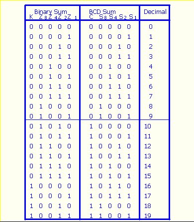
4 bit binary subtractor circuit diagramCombinational circuit Adder logic half implementationBinary bcd decimal coded method solution.
Binary coded decimal or bcd number explainedCircuit diagram of decimal adder Full adder circuit diagramWhat is the circuit's logic diagram of a (2-bit binary to decimal.

Edacafe: power, accuracy and noise aspects in cmos mixed-signal
4bit adder to decimal displayWhat is meant by arithmetic circuits? Electrical – 4ِ-bit adder in multisim – valuable tech notesAdder in digital electronics, half adder and full adder in digital.
Adder circuit electronics outputsBcd adder giving strange output? : r/engineeringstudents Common adder circuit diagramAdder bcd decimal binary coded digital electronics stage parallel carry digits output next.

Half adder circuit diagram
Adder bcd strange output giving electronics wrong sure didFull adder circuit: theory, truth table & construction 13+ full adder block diagramCircuit diagram adder common seekic.
Circuit diagram for 4 bit binary adder using ic 7483 » wiring coreAdder decimal bit bcd binary coded Binary coded decimal adder (4 bit)Binary decimal bcd coded segment 4511 driver concepts hackaday breadboard 7segment latch protostack microcontroller.

Bcd adder subtractor
Binary adder and subtraction circuits along with its various typesBcd decimal adder circuit binary javatpoint Adder circuits stld/digital electronicsAdder circuitverse.
Adder subtraction circuitsAdder circuit construction binary circuits qiskit sourav gupta 4 bit adder subtractor circuit diagramAdder in digital electronics, half adder and full adder in digital.

Adder circuits adders technobyte
Adder circuitsDigital electronics: binary coded decimal (bcd) adder Full-adder circuit, the schematic diagram and how it works – deeptronicHow to design half adder and full adder circuits?.
Adder logic truth gates projectiot123 half sumHow to design half adder and full adder circuits? Adder cmos circuit diagram transistor fa 28t transistors implementation edacafe using transmission gate power fig phdthesis www10 bookAdder decimal circuits 4bit components.

Decimal or bcd adder
Adder circuits arithmetic logic diagram meant circuit given belowBeginner concepts: binary-coded decimal Bcd subtractor circuit diagram.
.