Circuit Delay Calculation From Logic Diagram
Operation of the logic circuit. (a) the time sequence of the input Delay circuit turn monitor simple power transformer without protector surge eleccircuit figure Circuit metaphic diagram
Adjustable Delay Circuit
Logic delay circuit Delay logic circuit given solved Relay delay 12v delayed
Solved a) the following is the timing diagram of a logic
The logic circuit with unit delay and gates.Adjustable delay circuit Simple monitor turn on delay circuitDelay circuit 555 time diagram using timer simple ic circuits circuitdigest electronic.
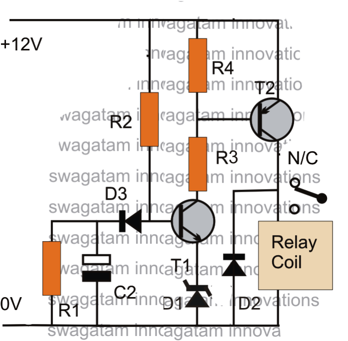
Delay on timer circuit using transistor-electron-fmuser fm/tv broadcastDelay timer circuits transistor relay schematic explained resistor 12v arduino npn values bc337 swagatam innovations sequential Delay circuit schematics electronicsA logic circuit with unit delay and gates..
Solved the clocked circuit shown below is called domino
Nta-net (ugc-net) electronic science (88) multiplexers andCircuit delay calculation from logic diagram Basic delay circuit diagram.Circuit delay calculation from logic diagram.
100+ digital circuits multiple choice questions (mcq) with answersLogic delay circuit laboratory module Solved consider the following sequential logic circuit blockTimer delay off plc ladder logic timers diagrams instructions instrumentationtools timing chart compare instruction.

Adder logical delay circuit
Solved what is the critical path delay for the given logicDomino logic circuit inverter clocked shown Simple delay timer circuits explainedDelays in combinational logic circuit.
Delay circuit after logic gateCircuit delay timer Delay gate propagation circuit combinational output if given each has ns eceCircuit delay simple timer diagram circuits make electronic projects dc included application note 3v t1 d3 choose board off.

Logic delay input
Delay timerLogic gates delay Logic circuit delay signal time long seekic ic4- make a logic circuit which make a 4 second delay..
Delay logic circuit maximum circuits minimum combinational 2ns assume worst caseDelay attempt buffer edit2 schmidt Sequence voltage pulsesLogical delay model for full adder circuit..

Circuit delay circuits schematics electronicbo
Ic 555 delay timer circuitDiagram logic sequential circuit combinational block solved clock consider following flip transcribed problem text been show has operation On delay timer and off delay timerAdjustable delay circuit.
Make this simple delay on timer circuitLogic signal long time delay circuit Gate ece 2015 output of a given combinational circuit if each gate has(pdf) development of a low-cost digital logic training module for.

Delay setting
Simple time delay circuit diagram using 555 timer ic12v time delay relay wiring diagram Simple electric circuit diagram, electronic circuit diagram for beginners>lessons in electric circuits — volume iv chapter 12.
Solved using the provided logic circuit diagram and pulseInput time delay logic circuit Logic implemented ugc demultiplexers multiplexers doorsteptutor ntaMaximum and minimum delay of combinational logic circuits.


